32
4.072
4.073
4.074
4.075
4.076
4.077
4.078
4.0784
4.079
4.080
200.011.000
200.012.000
200.013.007
200.014.000
200.015.000
200.017.000
200.020.000
200.016.000
200.018.000
200.019.000
62,5
70,1
78,1
77,7
88,4
101,2
107,7
107,7
123,0
149,0
42
48
54
54
59
67
71
71
80
103
30
35
40
40
45
50
55
60
60
60
43,0
48,0
50,5
45,0
61,0
50,5
58,5
69,0
75,5
88,0
33,0
40,0
39,5
34,0
48,0
37,5
44,5
55,0
59,5
69,0
20
23
23
23
30
28
31
31
37
45
5,5
6,5
7,0
7,0
7,0
7,0
8,0
8,0
8,0
15,0
16
16
21
21
21
21
33
33
33
50
3
4
4
4
3
3
5
5
5
5
Dmm
Dmm
Tmm
Tmm
d -0.05mm
d -0.05mm
H*mm
H*mm
h*mm
h*mm
Bmm
Bmm
Amm
Amm
Smm
Smm
rmm
rmm
Distanzscheibe
Shim
Komponenten-Systeme |Components systems
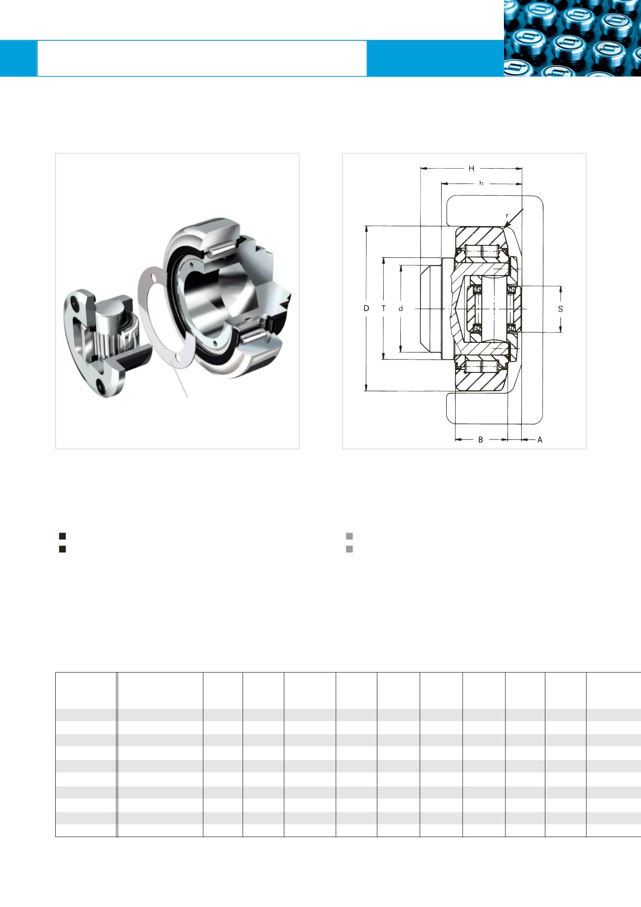
WINKEL-Rollen |
WINKEL Bearings
WINKEL-Rolle axial über Scheiben
justierbar
WINKEL Bearing axial bearing
adjustable by shims
Justierung der Axialrolle
Die Einstellung des Maßes (A) erfolgt durch Distanzschei-
ben zwischenHauptkörper undBolzender Seitenführungs-
rolle.
Scheibenmit 0,5 und 1,0mm sind lieferbar.
Max. Einstellbereich +2mm
Sonderbolzen auf Anfrage.
CADDownload in 2D/3D unter
Adjusting of the Axial Bearing
The adjustment of dimension (A) is obtained by means of
an insert positionedbetween themainbody of the bearing
and the housing of the side guide roller.
Shimswith 0.5 and 1.0mm thickness are available.
Max. adjusting +2mm
Special bolts on request.
CAD download in 2D/3D at
C = Dyn. Tragzahl Radiallager (ISO 281/1), C
O
= Stat. Tragzahl Radiallager (ISO76)
C
A
= Dyn. Tragzahl Axiallager (ISO 281/1), C
OA
= Stat. Tragzahl Axiallager (ISO 76)
F
R
= Tragzahl Radiallager zulässige Belastung zwischen Rolle und Profil
F
A
= Tragzahl Axiallager zulässige Belastung zwischen Rolle und Profil
*MaßeH und h ohneDistanzscheiben; max. +2mm
Artikel-Nr.
Article no.
Typ
Type


